This site shows my DIY work mainly at imaginative level.
Handmade water leak survey device
Handmade water leak survey device
In this document, I will show my hand made acoustic water leak survey device,the equipment which looks for the leak part of underground piping.
It was expected that it had some leaked water from a sound of a pump operation.
However, it was not found even if it heard it with the ear.
Since piping was under concrete, it was difficult to dig and search.
Since it had to search in a hurry, sufficient consideration and a design are omitted.
Therefore, the completeness of equipment is low.
However, since the leakage-of-water part was found, it introduces.
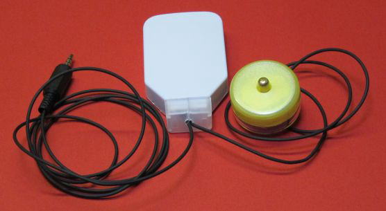
The schematic structure of equipment is as follows.
1. The sensor device is made using a piezo disk, piezoelectric ceramic. This device is made as to detect roughly 50 to 500Hz acoustic vibration.
2. The detected signal is amplified by some circuit.
3. The amplified signal is inputted into the mike input of a smart phone, and a visualized by the spectrum analyzer software for voice frequency.
Table of contents
1. Sensor plan
2. Select software
3. Make sensor
4. Make amplifier
5. Survey
6. Dig
Make believe (Assumption) section
1. Sensor plan
First of all, a sensor is made.
The piezo disk was taken out from the D27mm piezo-electric buzzer element.
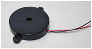
The piezo disk is usually made as for buzzer sound.
It seems that the resonance frequency of a piezo disk is about 3kHz in any size, since the maximum sensitive frequency of
human's ear is about 3 kHz.
And this frequency is too high for this purpose.
Various things were placed or pushed, the sonority condition of sound was heard, or output voltage measurement was carried out with the digital oscilloscope, get of an outline, and it decided to use the following structures. It is almost only by intuition.
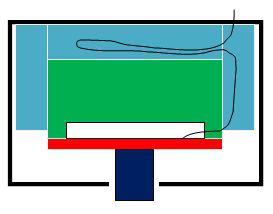
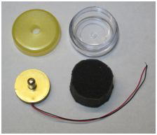
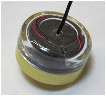
In inside, it is from a figure to order,
- low rebounding sponge (blue portion)
I tried to use gel rubber at first, though the buffer structure seems not good on the target frequency.
Then low rebounding sponge was used.
- dumping weight (green portion)
It does not fix to a container but floats by sponge.
- piezo disk (red portion)
- pickup projection (dark blue portion)
If weight is too heavy, ceramics are likely to be broken while in use, but if too light, the detection sensitivity of a
low frequency wave will be down.
The weight was 20 to 30 grams so that the sensitivity of the grade which is at least 200 Hz could be expected.
By estimates from the specific gravity of brass, the size of this weight is set to 27mm in diameter and
about 5 mm in thickness.
Adding 1 mm of the thickness of a surrounding projection part, thickness shall be 6 mm.
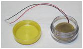
The cream case for a makeup stuffing substitute was used for the case of this sensor.
Interior space is 32 mm in diameter, and a depth of 17 mm.
2. Select software
The next is display software.
Since long time was required if made by oneself, what is used was looked for.
Although it is said proverbially, the secret of DIY is "not making if possible."
Although leakage-of-water sound is likely to come out comparatively regularly, since a sometimes quite loud environmental sound is mixed.
Then probably, not a real time or a peak hold but an integration display will be appropriate.
As what suits this, it decided to use voiceprint display software.
It is that which a horizontal axis calls time, a vertical axis calls frequency, and a color calls intensity.
Since "the capability to recognize the regularity of a pattern by the eye" of a human today is considered to be higher
than "the capability heard and divided with an ear", probably remarkable information will be acquired by this way.
Although free software was looked for, the software which can expand and display 50 to 500 Hz is not found.
Then it was quite big-ticket for an Android application, it decided to use SpectralView Analyzer PRO.
Actual making section
3. Make sensor
Since the weight should take care of only the degree of flat of the adhesion surface, it was roughly cutout from brass.
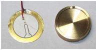
The piezo disk was picked out from the piezo-electric buzzer, and remove the adhesives to clean.
Since it was too poor soldering of a piezo disk from the first, a few was corrected.
The piezo disk was pasted up on weight by the epoxy adhesive.
The cooking sheet was used for the pasteboard of epoxy adhesion. This has very high cost performance.
Making too much indifferently, I forget to make a hole in the back of weight carelessly.
Is just the exit hole of an electric wire enough for breathing of air?
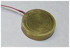
A projection is also cut out from brass and is pasted up by an epoxy adhesion.
Low rebounding sponge was cut and make the shape with scissors.
Sponge is cut in the shape of a cup so that the circumference of weight may be wrapped.
4. Make amplifier
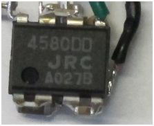
The amplifier circuit was made using the operational amplifier (NJM4580DD).
It is two steps of very fundamental inverting amplifier, and the gain is 470 times by 22k/1k and 47k/2.2k.
680 pF was connected to the prevention from an oscillation in parallel with the 1st step of 22k.
Moreover, 100 ohms was put into the output in series for protection of a smart phone.
Although it might be needlessness, since bias may have come out, a 10 micro F ceramic condenser was put into input and
output in series.
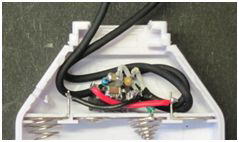
To avoid the noise by a boost circuit, I select to use the four battery operation ±3V.
The 100yen (about 1$) USB charge battery BOX was used for the battery case.
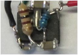
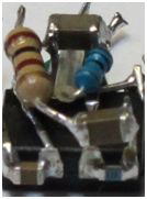
Since there were also few spaces and it was also troublesome to have made a substrate, SMD parts were used.
However, only resistance of an input and an output used parts with a large body.
Although this also has the calorific capacity as a protection function, the effect like a spring of structure is mainly
aimed at (since it connect to a cable).
Use section
5. Survey
This time, I also bought a stethoscope for the trial.
Although it was a double type for not a toy but medical treatments, it was useless at all.
The made device was effective.
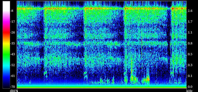
A lower figure is a result in the place where a reaction becomes large most.
The pump is operating intermittently.
Operation of a pump is only ON for 0.5 second at intervals of about 5 seconds.
On the screen, time is progressing toward the right from the left.
It is about 23 seconds from end to end.
A reaction becoming strong if the pump operates, and becoming weak gradually after a pump stops.
The next figure is a result at a place where 20cm away from the strongest reaction point.
The clear difference has come out.
It seems that a place can be pointed in quite narrow area.
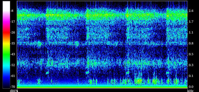
Conversely, almost no reaction at 1 m away.
By the time it found it, the most number of times had to measure.
Higher sensitivity may be better for the effective survey.
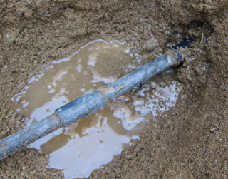
6. Dig
When digging, it was shifted about 15 cm from the strongest reaction point.
It seems that vibration reflected with the wall of horizontal concrete by side.
Though the detection accuracy about location was enough for my demand.
This is not a shop but my hobby.