This site shows my DIY work mainly at imaginative level.
Generator for a small wind power
DIY generator for a small wind power generation
I made a kind of axial air gap generator.Becasuse of I feel the NdFeB magnet (neo magnet) is too strong against the characteristic limit of "copper" coil,
I set the magnet not double side but single side of coil, and set a little larger air gap as about 1mm.
The ferrite core is inside the coil.
The magnet and coil is not a same number to get smooth rotation, and then this is 12 phase generator.
The diode is inside the generator, then the output is dc.
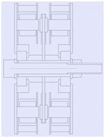
Follows drawings shows the structure. ( Some points are modified while making but roughly same.)
The magnets are set on the double side of rotator plate, and coils are set also on double side.
The core number and magnet number of each side is selected as not have a same prime number except 2.
And shift the angle of double side.
This is for smooth rotation of shaft by avoiding the synchronize of many magnet-coil pair at one time.
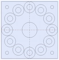
The magnet number should be even number, because S and N is set alternately to round.
Odd number of coil will be better for smooth rotation, but not good for the moment balance.
I select 12 for coil and 14 for magnet.
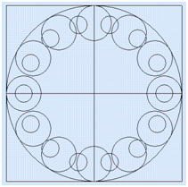
The magnet of double surface is set as shift the angle each other for smooth rotation.
The prime numbers of 12 are 2 and 3, and prime numbers of 14 are 2 and 7.
Then the minimum angle of synchronize core and magnet at one side is 360/(2*3*2*7)=360/84=4.29 degree.
Then I set the shift angle to 2.14 degree, as a half of this number.
I shift the magnet location, though you can shift the angle of coil instead of magnet.
And you can select odd number for coil and synchronize double side.
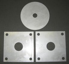
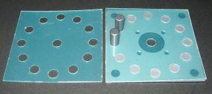
Rotator plate and stator plate are made from iron. I bought it from order made laser cut iron plate store.
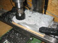
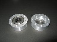
The bearing holder is made from aluminum plate by using CNC mill and lathe.
Bolt is made from stainless steel to get bigger magnetic resistance at shaft.
The spacer at shaft is brass.
To make a coil, I made a jig at first.
The jig is made from polyacetal not to stick an epoxy resin.
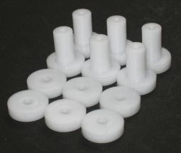
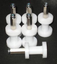
I know the polyester coated wire is better but I use 0.4 mm diameter poly urethane one because I have.
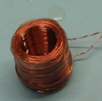
350 turns for each coil.
Before winding the wire, the polyethylene wrapping film is winding to the shaft of jig,
for easy slotting out the coil after.
The coil is stuck by the epoxy resin before removing from the jig.
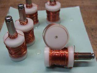
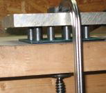
To make the jig for positioning the ferrite core. And the ferrite core glue to the iron plate by the epoxy resin.
You should use core in the coil to reduce the magnetic resistance,
because the air have very big magnetic resistance.
I use ferrite core because I got it easier, though the iron core can be used.
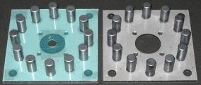
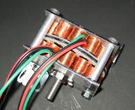
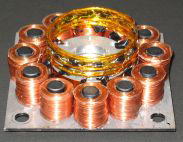
Setting the coil, and stuck by the epoxy resin. The photo is the one before epoxy.
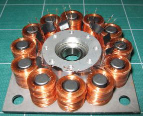
I use full-wave voltage doubler for a converter circuit.
It can make a many phase converter with simple structure, and save Vf loss at low generate voltage.
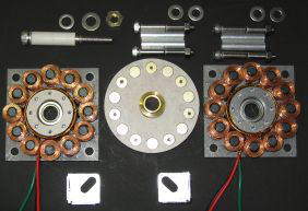
The photos shows the converter ring and its mounting.
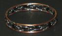
And all parts be together.

I bought an oscilloscope from China and then I measure the output.
Resistance load is connected between plus and minus output, and measure from ground output to plus.
The shaft is rotated by two fingers.
Left is 47 ohms, center and right are 10 ohms. Finger feel heavier at 10 ohms.
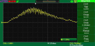
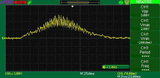
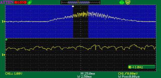
Roughly half rotate to release the shaft, then average 4rps (=240rpm) and 1.2V output.
I believe that this will be broken at less than 5000rpm, so I need to consider the maximum voltage up to 50V (because of doubler).
I measured the output voltage by using mini lathe.
The output voltage is averaged by chemical capacitor 68uF/50V.
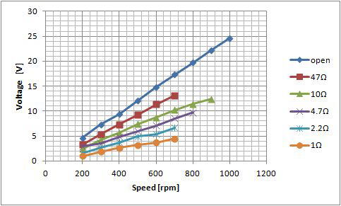
The output voltage seems suit for boost circuit.
This is not a shop but my hobby.